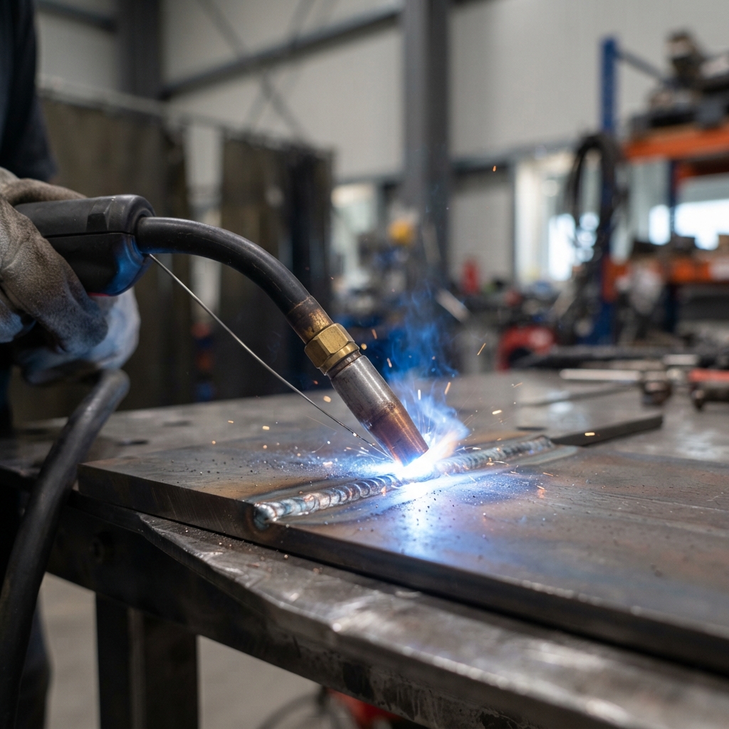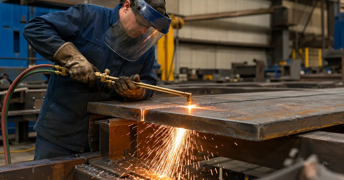


MIG welding porosity is shielding gas, moisture or contamination that was trapped in the weld pool and could not escape before the metal solidified, leaving voids inside or on the surface of the bead. In most shops it is not one bad setting but one broken link in a short chain: gas that never reached the arc cleanly, wire or plate that carried something into the pool, or a torch whose consumables were worn enough to disturb the gas shield. Because the defect is visible and repeatable, it is also one of the fastest weld problems to diagnose once you work through that chain in order.
This guide covers how to read the four common porosity patterns, a ten-minute diagnosis sequence that starts at the gas source and ends at the contact tip, the gas flow settings that cause most recurrences, why aluminum behaves differently, and how inspection codes decide whether a joint is actually a reject.
What Is MIG Welding Porosity?
MIG welding (GMAW) feeds a continuous solid wire electrode through a torch while a shielding gas flows around the arc. The gas displaces the atmosphere so the molten pool solidifies without absorbing nitrogen, oxygen, hydrogen or water vapor. Porosity is what remains when that protection fails: rounded cavities formed by gas that stayed in the metal instead of escaping.
In practice, MIG welding porosity appears in a few recognizable shapes, and the shape is the first diagnostic clue. Scattered porosity is spread evenly along the bead and usually points to a system-wide gas problem. Clustered porosity sits in one area and often marks local contamination or a start-and-stop. Wormholes, sometimes called piping, are elongated internal channels and are the signature of heavy gas contamination or moisture. Crater porosity appears only where the arc stopped.
The four common patterns at a glance
| Pattern | What you see | Most likely starting point |
|---|---|---|
| Scattered | Isolated round holes spread across the whole bead | Gas flow too low or too high, drafts, a leaking gas path |
| Clustered | Groups of holes in one section | Oil, paint, rust or moisture on that part of the joint; poor restart |
| Wormhole / piping | Elongated internal channels, often found by radiography | Severe gas contamination, wet or rusty wire, wrong gas |
| Crater | Holes at the end of the bead only | No crater fill, gas post-flow cut off too early |
What Causes MIG Welding Porosity?
The most common MIG welding porosity causes group into four families. Working through them in this order stops you from adjusting wire feed speed when the real problem is a cracked hose.
1. Loss of shielding gas coverage
This is the most common cause, and it has more than one form. Flow can be too low to fill the arc zone, or so high that the jet becomes turbulent and pulls surrounding air into the stream. A blocked nozzle, a worn contact tip, a leaking hose or solenoid, an empty cylinder and an open shop door all break the same shield in different ways. Welding outdoors or near a fan, a crane or an open bay door is enough to strip the gas away even when the regulator reads correctly.
2. Contamination on the wire or the plate
Oil, grease, coolant, paint, primer, adhesive, mill scale, rust and moisture all release gas when they meet the arc. So does a wire spool that has been open in a humid shop for months, or a liner that has picked up drawing lubricant. Galvanized and coated steel need specific handling because the coating itself vaporizes in the pool.
3. Consumables and torch condition
A MIG welding contact tip that is worn oval, a nozzle bridged with spatter, a kinked liner or drive rolls set too tight all change how the wire leaves the torch. When the wire wanders, the arc wanders with it and the gas shield no longer covers the pool. Consumables are cheap compared with a rejected part, which is why a fixed replacement interval usually pays for itself. The consumables supply chain guide covers how to keep tip, nozzle and liner specifications consistent between orders.
4. Parameters that outrun the gas shield
Excessive stick-out (contact-tip-to-work distance), too steep a torch angle, travel speed that leaves the pool exposed, and the wrong polarity can all produce porosity in an otherwise healthy setup. Solid-wire GMAW normally runs electrode positive (DCEP); the wrong polarity setting on a multi-process machine will change arc stability and gas behaviour at the same time.
Diagnose It in Ten Minutes: A Shop-Floor Sequence
Change one variable at a time and record what you changed. The order matters: check the gas path before touching the machine settings, because a setting adjusted to compensate for a leak will fail again as soon as the leak is fixed.
- Confirm the gas. Check the cylinder label and the mix against the job. A CO2 cylinder on a job set up for 75/25 argon-CO2 will run, and will weld badly.
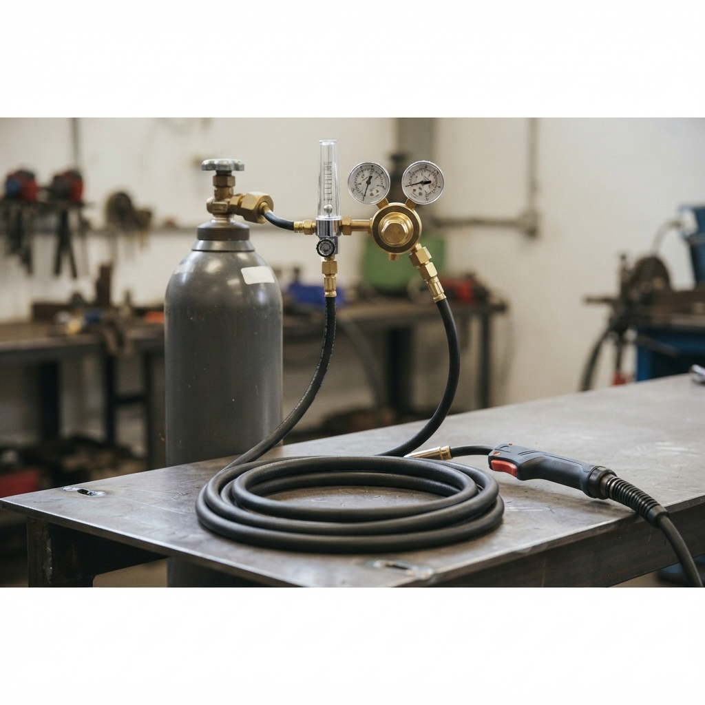
- Measure flow at the nozzle, not at the regulator. A flowmeter at the torch outlet shows what actually reaches the arc. A regulator gauge that reads a healthy pressure can still feed a restricted or leaking line.
- Leak-test the whole path. Soapy water on the regulator outlet, hose couplings, solenoid and torch connection. A small leak draws air in as the gas expands.
- Look into the nozzle. Spatter bridging the gas ports is common and easy to miss from outside. Clean or replace, then re-check flow.
- Inspect the contact tip and liner. Replace a tip with an oval or spatter-clogged bore, and replace a liner that is kinked, dirty or the wrong size for the wire.
- Check the wire. Look for rust, kinks, a loose spool, and drive-roll tension that either crushes the wire or lets it slip.
- Clean the joint. Grind or wire-brush at least 25 mm (about 1 in) either side of the weld line, and degrease before grinding so contamination is not pushed into the surface.
- Control the air around the arc. Close doors, screen the work area, and if you must weld in a draft, raise flow slightly and shorten stick-out rather than opening the gas wide.
Shielding Gas Flow Rate: the Setting Most Often Wrong
Shielding gas flow rate is measured in cubic feet per hour (CFH) in the US and in liters per minute elsewhere. The usual shop error is not setting it too low; it is opening the regulator after a draft problem and creating turbulence that makes the porosity worse. Higher flow is not better coverage, and MIG welding porosity that gets worse when you open the valve is a turbulence problem, not a starvation problem.
| Application | Commonly used starting range | What changes it |
|---|---|---|
| Mild steel, 75/25 argon-CO2, short circuit | 15-25 CFH at the nozzle | Nozzle size, stick-out, drafts; below roughly 10 CFH coverage collapses |
| Mild steel, 100% CO2 | 15-25 CFH | CO2 runs hotter and spatters more; flow behaviour differs from mixes |
| Stainless steel, tri-mix | 20-30 CFH | Higher flows are often needed; verify against the machine maker's chart |
| Aluminum, pure argon | 20-30 CFH | Drafts and long stick-out hurt more; argon shielding is easily disturbed |
These are industry starting ranges, not a specification for any one machine. Use the setting chart for your power source and torch, then adjust in small steps while watching the bead. If the weld improves when you lower flow, you had turbulence, not starvation. If it improves only when you raise flow well above the chart, look for a leak or a partially blocked nozzle.
How to Prevent Porosity in MIG Welding: a Setup Routine
Prevention is mostly a short routine repeated at the start of every shift, plus a replacement schedule for the parts that wear.
- Start of shift: confirm gas type, set flow with a flowmeter at the torch, inspect the nozzle and tip, and run a 100 mm test bead on scrap from the same lot as the production plate.
- Every spool change: check wire for rust and kinks, blow out the liner, and confirm drive-roll tension with the wire stopped against a block.
- Weekly: leak-test fittings and hose, check the regulator for creep, and inspect the ground clamp and cable for a poor connection that heats under load.
- Per job: match gas and wire to the base metal, keep the joint dry, and note the settings that produced a clean bead so the next operator can repeat them.
For higher-volume cells, torch selection belongs in that routine too. Duty cycle, cable length and connector type decide whether a torch stays cool and stable through a shift, which is the subject of the production MIG torch guide.
Porosity in MIG Welding Aluminum
MIG welding aluminum porosity is more common than porosity in steel for two reasons. Aluminum's oxide layer holds moisture and absorbs hydrogen, and molten aluminum dissolves far more hydrogen than it can hold in the solid state, so any hydrogen present at solidification becomes bubbles. Arc cleaning action helps break the oxide, but it does not remove oil, coolant or water from a joint.
Practical countermeasures: degrease with a solvent first, then brush with a stainless brush reserved only for aluminum, and weld within a short window before the oxide reforms. Use argon rather than an argon-CO2 mix, keep the wire dry, and avoid dragging the torch through the puddle. Preheating damp or thick sections drives off surface moisture, and a slightly wider gas coverage helps on long, hot beads. If MIG welding porosity appears only on aluminum and nowhere else in the shop, the cause is usually the cleaning sequence or the wire, not the machine.
Moisture, Mill Scale and Coatings
Anything on the surface becomes gas in the arc. Heavy mill scale, oil-based layout dye, anti-spatter spray that has pooled in a joint, primer, galvanized coating and condensation on cold plate are all routine causes of clustered porosity. A common shop practice for damp or heavily contaminated plate is a light preheat to drive off moisture; published defect guides have cited roughly 200-220°F for this purpose, but the correct value depends on the material and the procedure you are working to.
Coated and galvanized steel needs an additional control: the coating produces fume as it burns off, so ventilation and respiratory protection matter as much as the weld quality. The US Occupational Safety and Health Administration sets mechanical ventilation requirements for welding and cutting in 29 CFR 1910.252; treat that as the floor, not the target.
Weld Porosity Inspection and Acceptance
Not every pore is a reject. Acceptance depends on the code the part is built to and the inspection method used. AWS D1.1 for structural steel and ISO 5817 for fusion-welded steel both set limits by discontinuity type, size and location, and radiography or ultrasonic testing will find internal porosity that visual inspection cannot. Two practical rules follow.
- Judge against the drawing and the code, not against a scrap bin. Record the applicable acceptance criteria with the job so inspection decisions are consistent between shifts.
- Fix the process before repairing the part. Grinding out and re-welding a porous joint without correcting the cause produces a second porous joint, and repeated repair can make a marginal part worse.
Track the defect rate by cause — gas, contamination, consumables, parameters — rather than by welder. After a few weeks the pattern usually shows one or two dominant causes, and those are where a small investment pays back fastest.
When the Problem Is the Torch, Not the Technique
If gas flow measures correctly at the regulator but the bead still shows scattered MIG welding porosity, the loss is happening between the machine and the arc. Worn or mismatched torches are a regular culprit, and the fix is often a like-for-like replacement rather than a new process.
Our 15AK MIG welding torch is a 150 A air-cooled torch sized for MIG200-class machines and specified for steel and aluminum work. For higher-output setups, the 24KD MIG MAG torch uses a 10 ft cable and a standard Euro quick-connect fitting for MIG-250PRO, MP200 and similar machines. On the gas side, the 1C008-0028 CO2/argon pressure regulator is a Russia-style unit with an integrated safety valve and shut-off valve, and an economical build for shops standardizing on one regulator family. All three are supplied wholesale and for OEM programs.
Specifications alone do not prove a torch is right for your cell. Duty cycle, cable length, connector and consumable availability decide whether it holds a stable gas shield through a full shift.
FAQ
What causes porosity in MIG welding?
In order of frequency: shielding gas that does not cover the arc (low flow, turbulence, leaks, blocked nozzle, drafts), contamination on the wire or plate (oil, paint, rust, moisture), worn consumables that disturb the wire path, and parameters such as excessive stick-out or wrong polarity.
Can too much gas cause porosity?
Yes. Excessive flow creates turbulence at the nozzle, and the turbulent jet pulls surrounding air into the shielding stream. If MIG welding porosity improves when you reduce flow, the original problem was turbulence, not starvation.
Why do I only get porosity at the start of a weld?
Gas pre-flow is usually too short, or the nozzle is still outside the joint when the arc starts. Increase pre-flow slightly, start with the nozzle over the joint and establish the puddle before moving.
Does rusty or damp wire cause porosity?
It does. Rust, drawing lubricant and absorbed moisture all release hydrogen in the arc. Store spools sealed and dry, discard rusty wire, and check that the liner is not carrying dirt into the torch.
Why is aluminum more prone to porosity?
Aluminum's oxide layer holds moisture and absorbs hydrogen, and molten aluminum cannot retain much hydrogen as it solidifies. Cleaning sequence, dry wire and pure argon shielding matter more than machine settings.
Is any porosity a reject?
No. Acceptance is set by the applicable code and the inspection method. AWS D1.1 and ISO 5817 both allow defined limits depending on discontinuity type, size and location, so check the drawing and acceptance criteria before scrapping a part.
How do I check gas flow at the torch?
Fit a flowmeter at the nozzle outlet and read the flow while gas is flowing, not at the regulator gauge. This shows what actually reaches the arc and immediately separates a supply problem from a delivery problem.
Conclusion
MIG welding porosity is a gas-delivery and cleanliness problem far more often than a mystery of settings. Read the pattern first, then check gas type and flow at the nozzle, leak-test the path, inspect tip, nozzle and liner, clean the joint, and control the air around the arc. Once a bead runs clean, write the settings down and make the checks part of the shift routine so the defect does not return with the next spool.
If you have traced MIG welding porosity back to a worn torch, a blocked nozzle or a regulator that will not hold flow, our team can help you match a replacement to the machine you already run. Send the model, connector type and duty cycle through our contact page and we will confirm what fits.