

Production-floor answer
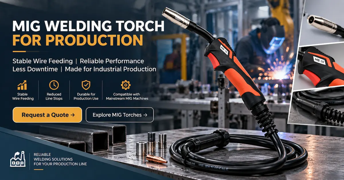
Which MIG welding torch is best for production? There is no universal model. Choose a MIG welding torch for production by matching the actual welding current and duty conditions, shielding gas, machine interface, wire diameter, cable routing and consumable system. Then verify handling and stoppage causes during a representative line trial. A higher model number is not a substitute for documented ratings or stable wire feeding.
For fabrication managers, welding engineers and industrial purchasers, the target is predictable operation and quick service—not merely the cheapest replacement gun. UWELD publishes 15AK, 24KD and 36KD air-cooled MIG/MAG torch references that buyers can assess against their equipment.
1. Why Production Welding Needs a Different Torch Decision
A torch used intermittently in a repair bay may never experience the same handling, cable routing or accumulated thermal demand as one moved between fixtures through an entire shift. In a production cell, a torch-related interruption can delay downstream operations even when the welding power source remains available. Frequent tip replacement, obstructed nozzles, uncomfortable handling and damaged cable assemblies can all disrupt planned output.
However, not every arc instability or stoppage comes from the torch. Wire quality, feeder settings, drive rolls, grounding, shielding gas, work preparation and power-source behavior also matter. The practical goal is to distinguish a torch fault from a wider welding-system issue before purchasing a replacement. Otherwise a factory can change torch models without removing the underlying cause of downtime.
This article focuses on line reliability and production management rather than the supplier-qualification and private-label revision topics covered by UWELD's separate MIG torch supplier guide and OEM SKU control guide.
2. Define Your Real Production Duty Before Choosing an Ampere Rating
The first purchasing input should be the welding procedure and actual usage pattern. Ask the welding engineer for working-current range, voltage, shielding gas, wire type and diameter, joint type, expected arc-on time, welding position and operating environment. A current rating stated without its test conditions cannot establish that a torch is suitable for a whole shift.
Duty cycle is the proportion of a defined reference period during which equipment is rated to operate under specified conditions. An advertised current value must be read together with its duty cycle, shielding gas and cooling method. The torch, power source, wire feeder and other equipment each have limits; the system must operate within the applicable ratings of all its components. Do not equate the power source's maximum output with the torch's permissible operating conditions.
| Production input | What to record | Why it affects the selection |
|---|---|---|
| Welding procedure | Actual current range, process, wire type, gas and joint | Establishes the operating conditions to be checked against the torch datasheet. |
| Production rhythm | Typical arc-on periods, pauses, shifts and stations | Distinguishes short repair work from repeated manufacturing use. |
| Installed equipment | Welder and feeder model/version, connector details | Prevents mechanical or electrical interface mismatches. |
| Physical layout | Fixtures, access restrictions, routing and working reach | Influences lead length, strain relief and operator handling. |
| Service expectations | Tip changes, line inspections, spare assemblies available | Determines how quickly the station can return to use. |
Selection rule: obtain the current datasheet for the exact offered torch assembly. Where rating, gas-specific conditions or duty cycle are not published on the product page, ask UWELD to document them before approving the installation.
3. UWELD 15AK vs 24KD vs 36KD for Production Evaluation
UWELD lists three MIG/MAG torch families with different published product identifiers. Their product titles establish certain configuration details, but they do not by themselves provide a complete, comparable set of duty-cycle ratings. The table below is therefore a shortlisting guide, not a performance ranking.
| UWELD product | Verified public description | Suitable next evaluation |
|---|---|---|
| 15AK MIG Torch | Air-cooled; listing title references 150 A and MIG200 machine. | Check intended repair/light fabrication or production duty against the complete rating and machine interface. |
| 24KD MIG/MAG Torch | Air-cooled; title specifies a 10 ft lead and Euro connector. | Assess reach, handling and documented rating for a defined fabrication station. |
| 36KD MIG/MAG Torch | Air-cooled; title identifies a Euro connector and CO₂/MIG/MAG category. | Request gas-specific current/duty data and trial conditions for more demanding proposed workloads. |
A 36KD model name does not prove unlimited continuous operation; a 15AK listing does not prove it is unsuitable for every production station. Fit and documented limits must decide. Also confirm the exact connector and machine version. A connector that looks similar is not proof that all feeder, gas and trigger interfaces are correct.
Send your machine model, working-current range, gas, wire diameter and shift pattern. Ask for a model-specific datasheet and sample quotation.
Request Production Torch Advice → See UWELD MIG Models →4. Wire Feeding: The Small Details Behind Unplanned Stops
A MIG torch guides consumable wire through a liner to the contact tip while also supplying welding current and shielding gas. When feeding becomes inconsistent, the operator may experience irregular arc behavior, wire drag or interruptions. Diagnosis must follow the whole route from the spool and feed rolls to the contact tip, rather than immediately blaming the torch.
Liner selection and cable routing
Confirm the liner is specified for the selected wire type and diameter. Incorrect or worn liners can increase resistance to feeding. Tight cable bends, routing around sharp fixtures and repeated twisting can make the situation worse. A production trial should assess the lead in normal working positions, not only laid straight on a bench.
Contact-tip fit and wear
Contact tips must match the approved wire and torch system. Wear, spatter and poor electrical contact may affect performance. Establish a clear replacement reference and investigate abnormal consumption rather than imposing the same time-based replacement interval on every welding application. Record the actual cause and frequency of changes.
Nozzle condition and shielding gas
Spatter buildup or damaged components around the nozzle can interfere with access and gas delivery. Shielding quality also depends on the regulator, supply, flow setup, drafts and application. Trained personnel should inspect and maintain the system according to the equipment instructions; increasing gas flow indiscriminately is not a reliable cure.
When the arc becomes unstable, record feeder behavior, wire condition, cable position, tip condition, gas delivery and power-source indications before assigning the fault to the torch. This creates evidence for a useful supplier discussion.
5. Ergonomics, Lead Length and Fixture Access
Operators may make hundreds of similar movements during repetitive fabrication. Torch weight distribution, trigger access, neck angle and the routing of the lead can influence fatigue and repeatability. An awkward assembly may be technically compatible yet difficult to position consistently around a jig.
A longer lead is not always better. Extra length can improve reach but also complicate routing and wire-feed behavior if handled poorly. Measure the actual distance and movement around the workstation. Check whether the 24KD's published 10 ft configuration reaches the work safely without pulling across edges or forming tight bends; request confirmation of other length options rather than assuming they exist.
Evaluate sample torches with normal gloves, fixtures and workpiece orientations. Record comments from more than one operator, including left- and right-handed access where relevant. Safety controls, guarding and extraction arrangements must remain intact during evaluation; do not modify controls to make a torch fit.
6. A Practical Pre-Shift and Planned-Maintenance Routine
Maintenance should be proportionate to the machine instructions, welding procedure and observed failure patterns. The following is a suggested operations checklist, not a UWELD-specific mandatory inspection schedule.
Before starting
Visually check the torch and lead for damage, confirm correct consumables, verify secure approved connections and remove the assembly from service if a safety defect is suspected.
During operation
Log abnormal wire feeding, unusual heating, damaged nozzles or recurring arc interruptions. Stop safely and follow the site's fault-isolation process.
At planned intervals
Inspect serviceable components as directed by the manufacturer. Review liner condition, contact-tip wear, lead routing and spare-part stock with qualified personnel.
After a recurring fault
Check the feeder, wire, tip, gas, power source and torch as a system; document the component or setting that actually resolved the issue.
Disconnect or isolate equipment as required by the applicable maintenance instructions before service. Consumables and damaged assemblies should be replaced with approved compatible parts. Avoid recommending improvised repairs or unsafe bypasses solely to keep a line moving.
7. Measure Downtime Before Claiming a Productivity Gain
Factories can use a simple event log to distinguish torch-related losses from general welding downtime. Suggested columns are workstation, shift, torch ID, fault category, stop start/end, verified cause, corrective action and part replaced. Over several shifts, the log may reveal whether the major issue is contact-tip consumption, liner trouble, cable handling or another subsystem.
Illustrative calculation: if a hypothetical station records four verified torch-related interruptions averaging six minutes, that equals 24 minutes of lost station time for that shift (4 × 6). It is not a UWELD performance estimate, nor does it prove that another torch would eliminate the loss. A replacement should be justified through matched trials and actual records.
| Metric | Suggested calculation | How to interpret it |
|---|---|---|
| Stop frequency | Verified torch-related stops / operating period | Shows whether interruptions are becoming more common. |
| Lost production time | Sum of verified torch-related stop minutes | Supports an operational cost discussion. |
| Consumable usage | Parts consumed / completed work or arc-on hours | Helps identify unusual wear or process changes. |
| Restoration time | Time to diagnose, service and safely restart | Shows the value of accessible parts and clear procedures. |
Changes in welding procedure, operator, wire batch or fixtures can distort a comparison. Record those differences in any before-and-after trial. The primary objective is reliable diagnosis and better purchasing decisions, not manufacturing an attractive savings percentage.
8. Plan Spare Assemblies and Consumables for Production Continuity
Even a well-matched torch requires servicing. Fabrication sites can reduce avoidable delays by maintaining an approved replacement assembly and clearly identified consumables for the installed model. Inventory must be tied to the precise connector, liner, contact-tip and nozzle system used on that station.
For operations purchasing, request an illustrated parts list and availability information with the initial torch quote. Separate fast-moving consumables from complete spare assemblies. If multiple 15AK, 24KD or 36KD configurations are used, avoid merging visually similar parts without verified cross-reference data. A correct replacement part available at the workstation is more valuable than a large stock of incompatible spares.
Production teams should also agree who may authorize a change of torch model or consumables. Uncontrolled substitutions can create both process and purchasing problems. The site's qualified welding personnel should review any changes that affect the validated welding setup.
9. How to Qualify a Torch in a Representative Production Trial
A shop-floor trial should answer a narrowly defined question: does the proposed configuration work with the specified equipment and welding procedure, and can it be operated and maintained as intended? It should not be a demonstration using unknown settings or conditions more favorable than actual production.
- Freeze the baseline: document machine model/version, wire, gas, welding procedure, current range, lead route and existing stoppage categories.
- Review documentation: obtain offered torch rating conditions, applicable safety information and compatible consumable references.
- Confirm the interfaces: check mechanical, gas and electrical/control compatibility before energizing equipment.
- Trial representative work: include normal fixtures, welding positions, handling and planned production rhythm under qualified supervision.
- Record observations: operator access, feeding behavior, tip changes, verified faults and maintenance time.
- Approve a defined configuration: document the model, lead, connector, consumables and conditions tested before issuing a production order.
IEC 60974-7:2019 addresses safety and construction requirements for arc-welding torches, including air-cooled variants. Reference to that standard explains a relevant technical framework; it does not mean every UWELD model has been independently certified to it. Request applicable model-specific evidence where needed for your market and site.
Share your welding procedure, equipment information and target order volume with UWELD. Confirm sample terms, documentation and the exact quoted assembly.
Ask for Samples & Datasheets → Review UWELD Purchasing FAQ →10. Compare Total Production Cost, Not Torch Price Alone
For a line manager, the relevant comparison includes the complete assembly price, compatible consumables, planned maintenance labor, verified disruption time and the cost of holding spares. A low purchase price may be attractive, but it cannot compensate for poor machine fit or an unavailable service part. Conversely, a more expensive torch is not automatically more productive.
Ask suppliers to quote the same cable length, rear connection, cooling method and supplied consumables. UWELD states that technical datasheets can be requested and that sample and lead-time details depend on the item and order. Do not publish a fixed MOQ, manufacturing lead time or performance guarantee for a model without written confirmation.
A useful RFQ should include current working conditions, shielding gas, feeder/welder models, target stations, lead length, consumption history, sample requirements and estimated annual demand. The resulting quotation can then be reviewed by engineering, maintenance and purchasing rather than being judged by unit price alone.
11. MIG Welding Torch for Production: Buyer FAQ
Is a 36KD MIG torch always better than a 24KD for production?
No. Evaluate each offered configuration's documented rating, duty conditions, gas, connection, weight and handling against the actual workload. Model naming alone cannot establish line suitability.
Can the UWELD 15AK be used in manufacturing?
Potential applications depend on the specific machine, welding procedure and documented torch limits. The product listing identifies an air-cooled 15AK and references 150 A/MIG200, but production suitability still requires technical review.
What causes frequent MIG wire-feeding stops?
Possible causes include feeder/drive-roll problems, wire condition, liner wear, cable bends or contact-tip mismatch. Troubleshoot the full feeding system before concluding that the torch assembly is defective.
How should I choose the cable length for a fabrication line?
Measure movement around the actual fixture and avoid unnecessary routing, strain or tight bends. Verify which lengths and connectors are offered for the exact model.
When should contact tips and liners be replaced?
Follow equipment instructions and documented condition or wear indicators. Actual service needs depend on process, consumable fit and operating conditions; one universal replacement interval is not appropriate.
Can UWELD provide samples and technical documents?
UWELD's FAQ says product samples and technical datasheets are available by request; sample/shipping costs and report availability depend on the model and project. Contact the team with exact product references.
How can procurement reduce production interruptions?
Specify the torch correctly, qualify it under real workload, identify compatible spares, train personnel in appropriate inspection and log verified stop causes before evaluating changes.
Conclusion
The right MIG welding torch for production is the assembly that matches the line's documented operating conditions, supports stable wire feeding and can be serviced without unnecessary delay. Compare UWELD's 15AK, 24KD and 36KD against your actual machines and duty requirements—not generic amperage assumptions. Confirm model-specific specifications, run a representative trial and stock the correct consumables before volume purchasing.
Request a Production MIG Torch Quote → Browse UWELD MIG Torches →